+86 13163919000
 info@xinmeiintelligent.com


Choosing a CNC drilling tapping center manufacturer is fundamentally a decision about production reliability.
A factory may purchase a machine because its existing drilling process is too slow, its tapping operations create inconsistent threads, or its operators spend too much time transferring parts between machines. Yet a machine that looks capable in a catalog can behave very differently when machining thousands of components under actual factory conditions.
The difference often comes from decisions that are not obvious in a specification sheet: machine-frame rigidity, spindle integration, axis alignment, thermal behavior, fixture design, CNC control configuration, cutting-tool selection, and the manufacturer's testing procedures.
Consider a manufacturer producing brass valve bodies. A faster spindle may shorten part of the drilling cycle, but it cannot compensate for inaccurate workpiece location, poor chip evacuation, unstable tapping, or lengthy manual loading. Similarly, an automotive component factory may achieve acceptable results during a short demonstration and still encounter dimensional drift or tool failures during extended production.
For industrial equipment buyers, the important question is therefore not simply “Who can manufacture a CNC drilling and tapping machine?”
It is:
“Which manufacturer can engineer, assemble, validate, and support a drilling and tapping center that meets our actual production requirements?”
This guide addresses that question from a manufacturing and production-engineering perspective. It explains what a genuine machine manufacturer should control, how a drilling and tapping center is developed, which technical details influence performance, and what evidence buyers should request before approving an investment.
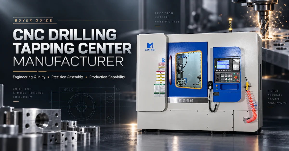
What Does a CNC Drilling Tapping Center Manufacturer Do?
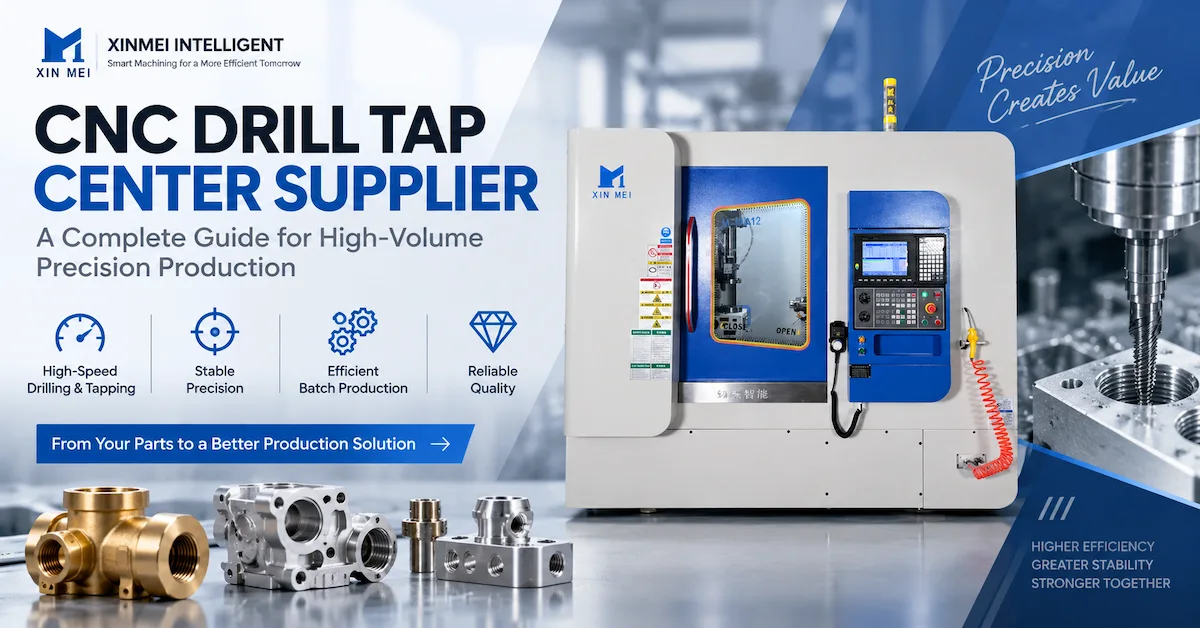
A CNC drilling tapping center manufacturer develops and produces numerically controlled machine tools designed to perform drilling, tapping, and related machining operations with controlled positioning, repeatability, and production efficiency.
Depending on its business model and engineering capabilities, a manufacturer may be responsible for machine design, component specification, structural assembly, CNC system integration, spindle installation, electrical integration, testing, application engineering, and final equipment validation.
The exact manufacturing scope varies between companies.
Some manufacturers produce major structural components internally. Others purchase castings, spindles, guideways, controllers, or other specialized parts and perform engineering, assembly, calibration, and final validation within their own facilities.
Neither arrangement automatically determines machine quality.
What matters is whether the manufacturer controls the critical engineering interfaces and can verify the performance of the completed machine.
A qualified CNC drilling and tapping center manufacturer should be able to explain:
-
How the equipment is configured for the workpiece.
-
How structural rigidity and machine geometry are controlled.
-
How the spindle, feed axes, and CNC system work together.
-
How drilling accuracy and tapping quality are verified.
-
How machine performance is tested before shipment.
-
Which components are standardized and which can be customized.
-
How engineering support continues after installation.
Manufacturers with broader application-engineering capabilities may also support dedicated fixtures, multiple-spindle configurations, robotic loading, and integrated machining lines.
For example, XINMEI Intelligent develops CNC machining equipment and production solutions for industrial components, with a product range extending from vertical drilling and tapping machines to multi-spindle machining equipment and integrated automation.
This combination is relevant to buyers who need more than a general-purpose machine.
CNC Drilling Tapping Center Manufacturer vs. Machine Supplier: What Is the Difference?
The terms manufacturer and supplier frequently overlap in industrial equipment purchasing, but they do not necessarily describe the same capabilities.
A machine supplier primarily provides equipment to the customer. It may also handle sales support, logistics, installation, and technical coordination.
A manufacturer has direct responsibility for at least part of the machine's engineering, production, assembly, testing, or manufacturing management.
The distinction becomes particularly important when the buyer requires customized equipment or project-specific acceptance testing.
| Evaluation Area | Trading Supplier | Engineering-Focused Manufacturer |
|---|---|---|
| Machine selection | Based mainly on available models | Based on machine capability and process requirements |
| Structural design | Usually limited influence | May participate in structural configuration and design |
| Machine assembly | Usually performed by another factory | Can control its own assembly process |
| CNC integration | Often depends on original manufacturer | Can coordinate electrical, drive, and control integration |
| Fixture development | May outsource | May provide engineering or coordinated customization |
| Production testing | Relies on supplier documentation | Can participate directly in testing and validation |
| Equipment customization | Limited or externally coordinated | Depends on internal engineering capability |
| Technical problem resolution | Often requires a third party | May provide more direct engineering access |
This comparison is not intended to suggest that every trading company provides poor service or every manufacturer provides excellent engineering.
Buyers should verify the actual responsibilities of the company supplying the equipment.
Ask who designs the proposed machine configuration, who performs final assembly, who approves component substitutions, who conducts accuracy testing, and who remains responsible if the machine does not meet agreed acceptance criteria.
These questions reveal much more than the label printed on a company's business card.
Which Factories Benefit Most From Manufacturer-Engineered Drilling and Tapping Centers?
A CNC drilling and tapping center is especially valuable when hole-making and threaded features account for a substantial share of the machining process.
Typical buyers include:
-
Valve and sanitary ware manufacturers.
-
Automotive and motorcycle component factories.
-
Door closer and floor spring manufacturers.
-
Precision hardware producers.
-
Industrial connector manufacturers.
-
Pump and fluid-control component manufacturers.
-
Machinery-parts suppliers.
-
Metalworking factories producing repeatable components in medium or large batches.
However, production volume alone does not determine the correct machine.
Part geometry, material, hole depth, thread size, dimensional requirements, setup frequency, and desired flexibility are equally important.
Suitable Production Conditions
A high-speed drilling and tapping center often makes sense when:
-
The same or similar components are manufactured repeatedly.
-
Drilling and tapping are major operations.
-
Fast tool changes and positioning are valuable.
-
The workpieces are compatible with the machine's size and load capacity.
-
Light milling or chamfering must be combined with hole-making.
-
The factory needs predictable batch-production performance.
Applications That Require Another Solution
A conventional drill tap center may not be the best choice when heavy rough milling dominates the cycle, the workpiece is exceptionally large, or several machining faces require extensive repositioning.
For highly repetitive components with many similar holes, a dedicated multi-spindle machine may be more appropriate.
For complex parts requiring heavy cutting and broader machining flexibility, another type of machining center may perform better.
A capable manufacturer should make these distinctions during application review instead of automatically proposing its most popular model.
How Does a CNC Drilling and Tapping Center Manufacturer Develop a Machine?
The manufacturing process should begin with a technical requirement, not with the assembly line.
Although the exact workflow varies by manufacturer and project, the following stages represent a practical framework for evaluating machine-building capability.
Stage 1: Workpiece and Production Requirement Analysis
The manufacturer first needs to understand the actual machining application.
Relevant information includes:
-
Workpiece dimensions and material.
-
Blank condition and manufacturing process.
-
Hole quantity, diameter, and depth.
-
Thread sizes and tolerances.
-
Number of machining faces.
-
Surface requirements.
-
Monthly or annual production volume.
-
Current machining method.
-
Required cycle time.
-
Planned operating shifts.
A workpiece drawing provides the basis for discussing what the machine must accomplish.
Without it, a quotation is largely a comparison of generic equipment specifications.
Stage 2: Machining Process Engineering
Next, engineers determine the operations required and the order in which they should occur.
A component may require spot drilling, drilling, boring, chamfering, tapping, and light milling.
The manufacturer should decide which operations can be combined, which require separate setups, and where tool changes or handling operations create avoidable delays.
A practical process plan also identifies the critical features that must be measured after machining.
XINMEI's technical resources explain the importance of CNC machining process planning in improving stability and manufacturing efficiency.
Stage 3: Machine Configuration Selection
The manufacturer then selects an appropriate equipment architecture.
Possible approaches include:
-
A conventional vertical drilling and tapping center.
-
A machine with a fast turret tool system.
-
A dual-spindle machining configuration.
-
A horizontal multi-spindle drilling and tapping system.
-
A dedicated machine for repeated part features.
-
An automated CNC production cell.
The choice must balance machining flexibility, production capacity, investment, maintainability, and the expected product life.
Stage 4: Mechanical Structure and Component Planning
The engineering team defines the mechanical arrangement, including machine structure, spindle layout, axis travel, guideways, drive systems, worktable, enclosure, and supporting components.
This stage is important because the mechanical architecture determines the machine's basic stiffness, movement behavior, accessibility, and potential for future automation.
Stage 5: Mechanical Assembly
The machine is assembled according to its engineering requirements.
Critical activities may include:
-
Mounting mechanical structures.
-
Installing guideways and drive systems.
-
Aligning the feed axes.
-
Installing the spindle assembly.
-
Checking movement resistance.
-
Adjusting mechanical interfaces.
-
Verifying lubrication and supporting systems.
Even accurately manufactured components can produce a poorly performing machine if assembly and alignment are not controlled.
Stage 6: Electrical and CNC System Integration
Mechanical assembly is followed by control-system integration.
The CNC controller, servo drives, motors, electrical cabinet, sensors, machine interfaces, and safety-related functions must work together.
For drilling and tapping equipment, stable synchronization between spindle motion and feed-axis behavior is especially important.
Stage 7: Calibration and Functional Inspection
Engineers evaluate axis movement, positioning behavior, machine geometry, spindle operation, tool changing, and control functions.
The objective is to identify mechanical or electrical deviations before application testing.
Stage 8: Trial Machining and Production Validation
A machine that moves accurately without a cutting load still needs to prove its ability to produce acceptable parts.
Trial machining evaluates the complete process, including workholding, cutting tools, actual material, machining program, coolant, and inspection.
For batch-production projects, the manufacturer should also discuss the duration and conditions of continuous-operation tests.
Stage 9: Final Inspection and Delivery Preparation
Before shipment, the completed machine should undergo an agreed final inspection.
Testing records, approved configuration details, installation requirements, and relevant documentation should be organized for the buyer.
XINMEI describes a structured manufacturing quality process covering component verification, assembly-stage control, final machine validation, and in-house equipment testing on its Quality Assurance page.
The buyer should translate this general quality approach into measurable requirements for the purchased machine.
Why Machine Structure Is a Major Manufacturing Quality Indicator
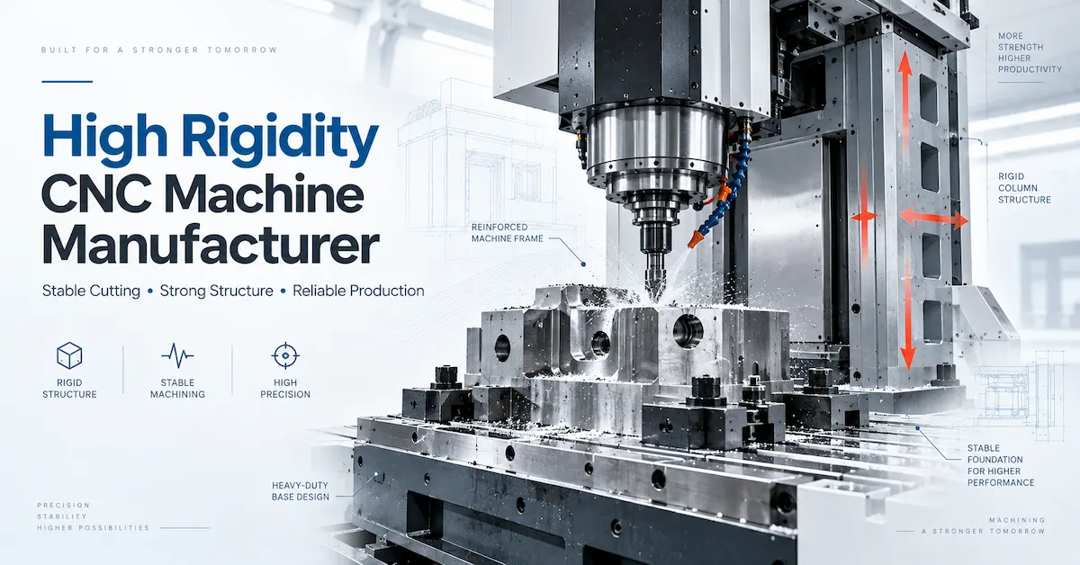
Machine rigidity influences how cutting forces are transferred through the spindle, tool, workpiece, fixture, and supporting structure.
A CNC drilling and tapping center may prioritize high-speed movement, but its structure must still resist vibration and maintain stable geometry.
Important areas include the machine base, column, spindle mounting, guideways, table, and connection points between major assemblies.
When the structure is insufficiently rigid, machining problems may become more visible through:
-
Poor hole-position repeatability.
-
Increased vibration.
-
Unstable surface quality.
-
Premature cutting-tool wear.
-
Problems during side milling.
-
Dimensional variation under changing cutting loads.
A rigid structure alone does not guarantee precision.
Thermal effects, alignment, servo behavior, tool condition, workholding, and cutting parameters also matter.
Nevertheless, structural engineering determines the foundation on which those other systems operate.
What Should Buyers Ask About the Machine Frame?
Useful questions include:
-
How is the structural arrangement selected for the machine's intended cutting operations?
-
What assembly inspections are performed?
-
How is spindle-to-table geometry verified?
-
What measures are used to control vibration?
-
How is accuracy checked after the machine has reached operating temperature?
-
Can the manufacturer explain the difference between unloaded positioning tests and actual cutting performance?
A serious manufacturer's answer should connect machine design to the workpiece rather than rely only on descriptions such as “heavy-duty structure” or “high rigidity.”
Spindle Engineering: Why Maximum RPM Is Not Enough
The spindle is one of the most visible specifications in a CNC drilling and tapping center.
Its rated speed matters, but the maximum RPM printed in a catalog does not describe the complete spindle system.
Manufacturing buyers also need to evaluate:
-
Applicable speed range.
-
Spindle power and torque behavior.
-
Acceleration and deceleration.
-
Bearing arrangement.
-
Toolholder interface.
-
Spindle runout.
-
Thermal behavior.
-
Lubrication and cooling provisions.
-
Suitability for the planned cutting operations.
A spindle optimized for high-speed drilling may not be the best configuration for demanding low-speed cutting.
Similarly, an application requiring repeated tapping cycles may place importance on synchronization and reversal characteristics.
Buyers should request performance information relevant to their material and tool sizes.
How Should Spindle Capability Be Verified?
A useful evaluation includes more than a no-load spindle demonstration.
Where practical, the acceptance test should include representative drilling, tapping, and other operations using the agreed cutting tools and material.
The manufacturer should be able to explain whether the proposed machine can complete the specified process without excessive vibration, overheating, poor thread quality, or unacceptable tool wear.
If the supplier cannot evaluate the application beyond maximum spindle speed, the engineering review is incomplete.
How CNC Control and Rigid Tapping Affect Thread Quality
Tapping requires coordinated movement between the spindle and the feed axis.
In a rigid tapping process, spindle rotation and axial feed must remain synchronized according to the thread pitch.
For a metric thread, the basic relationship is:
Axial feed rate (mm/min) = Thread pitch (mm/revolution) × Spindle speed (rpm)
This relationship illustrates why tapping is not merely another drilling movement.
The selected control system, drive tuning, spindle behavior, and programmed cycle must support the process.
However, the formula alone does not establish suitable cutting conditions. Tool manufacturers' guidance, workpiece material, thread geometry, hole preparation, and machine capability must also be considered.
Common Causes of Unstable CNC Tapping
Thread defects may arise from:
-
Incorrect pre-drilled hole diameter.
-
Inappropriate tap geometry.
-
Insufficient lubrication.
-
Poor chip evacuation.
-
Excessive tool runout.
-
Incorrect programming.
-
Unstable workpiece clamping.
-
Inadequate synchronization.
-
Incorrect tool-life assumptions.
For blind holes, chip accumulation and thread-depth control become particularly important.
For stainless steel, tool wear, heat, and material behavior may create additional challenges.
The machine manufacturer should be prepared to discuss these variables instead of treating tapping quality as a simple consequence of installing an expensive controller.
Buyers who want to understand common cycle structures can also review XINMEI's technical guide to CNC drilling and tapping cycles.
Why Fixture Engineering Belongs in the Manufacturer Evaluation
The machine may position its axes accurately, yet the finished part can still be outside tolerance if the fixture does not locate and support the workpiece consistently.
This is especially relevant to cast valve bodies, irregular automotive housings, thin-walled parts, and components with several machining faces.
A production fixture should control workpiece position without causing unnecessary deformation.
It also needs to provide tool access, chip clearance, and a reasonable loading procedure.
Important Fixture Design Questions
A manufacturing engineer should ask:
-
Which surfaces establish the machining datums?
-
How are casting or blank variations accommodated?
-
How is clamping force applied?
-
Could the fixture distort the workpiece?
-
Can chips interfere with locating surfaces?
-
Are manual adjustments required between cycles?
-
Can the fixture support multiple parts?
-
Can it accommodate a future robot-loading system?
These details often determine whether a technically capable drill tap center achieves stable output.
For high-volume parts, fixture engineering can also influence the number of workpieces machined per cycle.
That is why the machine and fixture should be treated as one coordinated manufacturing system.
XINMEI provides further technical background on CNC fixtures and workholding accuracy.
Single-Spindle, Dual-Spindle, and Multi-Spindle Machines: What Should Manufacturers Offer?
A drilling and tapping center manufacturer should not assume that every factory needs the same spindle arrangement.
The correct configuration depends on production volume, hole layout, process flexibility, and available capital.
| Machine Configuration | Main Production Strength | Most Suitable Situation | Primary Consideration |
|---|---|---|---|
| Vertical drilling and tapping center | Flexible drilling, tapping, and tool changes | Mixed and repeatable small-to-medium components | Tool capacity and process sequence |
| Dual-spindle machining center | Potential for parallel machining | Repeated parts with compatible operations | Fixture layout and process balance |
| Multi-spindle drilling and tapping machine | Simultaneous processing | Stable high-volume production | Part compatibility and spindle arrangement |
| Multi-station dedicated machine | Multiple operations distributed across stations | High-volume, relatively stable products | Initial engineering and changeover |
| CNC and robot production cell | Reduced manual handling | Repeated production with labor or utilization constraints | Integration and recovery procedures |
The advantage of multi-spindle machining is not simply that a machine contains more spindles.
It is the ability to perform useful operations in parallel.
For example, if a component contains several appropriately positioned holes, a multi-spindle configuration may complete more than one drilling operation during the same cycle.
However, simultaneous cutting is valuable only when the workpiece geometry, tool arrangement, stiffness, power, and fixture support allow it.
XINMEI's Vertical Drilling and Tapping Center
XINMEI's Vertical CNC Drilling and Tapping Machine is positioned for high-speed drilling and tapping, with a rigid machine structure, rapid turret tool changes, a compact vertical arrangement, and suitability for repetitive industrial production.
It is relevant for buyers seeking a versatile drilling and tapping platform for components such as hardware parts, plumbing products, and automotive components.
XINMEI's Six-Spindle Drilling and Tapping Machine
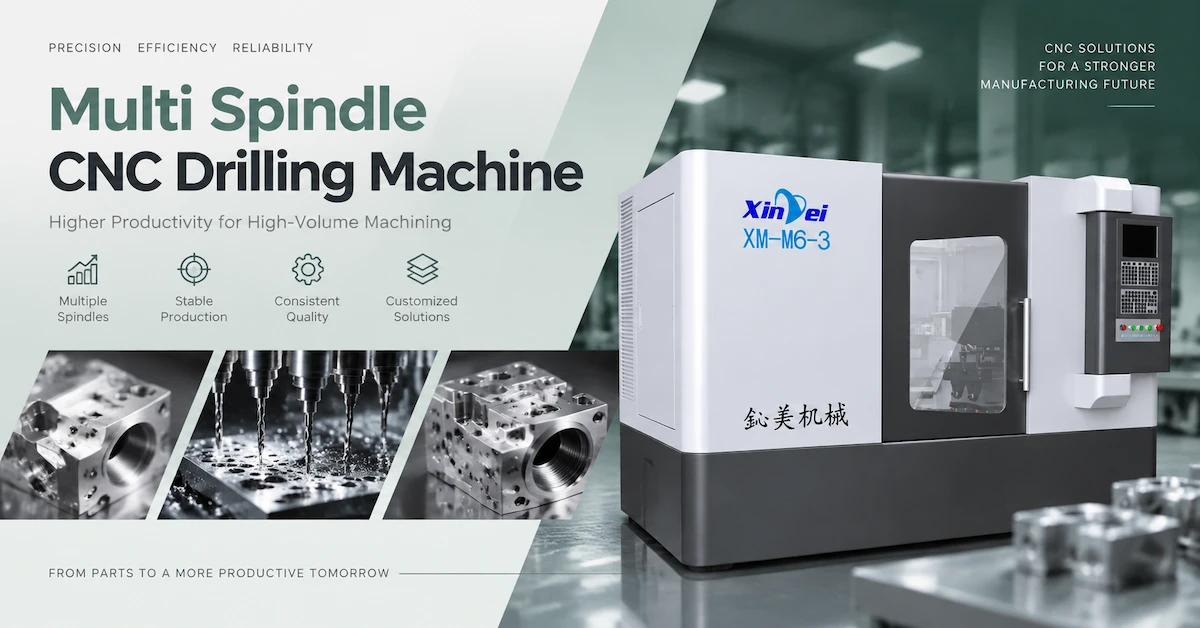
For repeated multi-hole applications, XINMEI also provides a CNC Horizontal Lifting Six Spindle Drilling and Tapping Machine.
The product page describes six-spindle simultaneous machining, a horizontal layout with a lifting column, a servo-driven tool-changing system, HIWIN linear guideways, and a fully servo-driven configuration without hydraulic components.
These are useful engineering characteristics, but the actual production benefit must be evaluated using the buyer's workpiece and process.
A six-spindle machine should not be presented as six times faster than a single-spindle machine without controlled comparative testing.
Tool engagement, loading, indexing, fixtures, and process balance all influence the result.
How Does Material Selection Affect Drilling and Tapping Center Design?
Manufacturers working with different materials require different cutting strategies.
Machine selection should therefore begin with the actual workpiece material, not a generic statement that the machine can process metal.
Aluminum Components
Aluminum applications may benefit from high spindle speed, rapid positioning, and efficient tool changing.
Important issues include chip evacuation, burr formation, tool adhesion, surface condition, and the specific alloy being machined.
Brass and Copper Alloys
Brass valve and plumbing components often contain repeated drilled and threaded holes.
The manufacturer should evaluate chip behavior, tool geometry, fixture location, thread specifications, and the possibility of parallel machining.
Stainless Steel
Stainless-steel drilling and tapping may require more careful consideration of tool wear, heat generation, lubrication, and cutting stability.
A machine demonstrated only on aluminum should not automatically be assumed to perform equally well on stainless steel.
Cast Iron
Cast-iron components may introduce different concerns involving abrasive wear, dust, chip management, and machine protection.
The manufacturer's application review should identify these conditions before selecting tooling and auxiliary systems.
Why Material-Specific Testing Matters
Even within one material category, different grades and blank conditions can change machining behavior.
A reliable manufacturer should therefore confirm the actual material specification and consider representative trial machining where the application warrants it.
Industrial Applications: How Manufacturing Requirements Change by Industry
The value of a CNC drilling tapping center is best understood through the parts it must produce.
Valve and Sanitary Ware Manufacturing
Factories producing valve bodies, faucets, manifolds, angle valves, and water-control components frequently perform drilling, tapping, and multi-face machining.
A common difficulty is coordinating several operations while maintaining consistent hole positions and threads.
The manufacturer may need to evaluate whether a vertical drilling and tapping center is sufficient or whether a multi-spindle or dedicated machine would improve throughput.
For brass castings, the fixture must also accommodate the realities of raw-part variation.
Typical purchasing priorities: cycle consistency, tooling cost, workholding stability, thread quality, and output per shift.
Automotive and Motorcycle Components
Brake-pump components, steering-system parts, cylinder-related components, and suspension parts may require controlled machining and documented dimensional verification.
The manufacturing discussion should address not only nominal accuracy but also production repeatability.
For example, a single acceptable sample does not demonstrate that the process will remain stable during a long production run.
Automotive buyers should request clearly defined inspection procedures and, where required, process-capability evidence.
Typical purchasing priorities: dimensional repeatability, machine availability, traceability requirements, stable tooling, and production validation.
Door-Control Manufacturing
Door closer housings, floor spring bodies, and related hardware may contain multiple holes and functional surfaces.
Some applications are more suitable for conventional CNC equipment, while stable high-volume parts may justify a dedicated machining concept.
XINMEI publishes a door closer machining application case illustrating its focus on the production of door closer housings and critical functional features.
For buyers, application references can be useful evidence of the manufacturer's industry focus.
However, they should not replace a trial or engineering review for a new workpiece.
Precision Connectors and Industrial Hardware
Small connector bodies, electrical components, and precision hardware may require many accurately positioned holes.
Important factors can include workpiece rigidity, tool runout, burr control, fixture repeatability, and production flexibility.
A compact drilling and tapping center may be appropriate, provided that the manufacturer's proposed spindle and fixture arrangement match the component.
Pump and Fluid-Control Components
Pump housings and fluid-control parts may contain holes that interact with sealing surfaces or internal passages.
Process planning should address drilling access, burr control, hole position, and inspection of the features that affect assembly or functional performance.
In these applications, dimensional quality can be more important than achieving the shortest possible isolated machining cycle.
Custom CNC Drilling and Tapping Centers: What Can Be Engineered?
Not every customer needs a completely new machine.
Customization often begins with the application around an existing platform.
Potential project elements include:
-
Worktable or fixture configuration.
-
Clamping arrangements.
-
Tooling packages.
-
Machining programs.
-
Spindle arrangement.
-
Part loading and unloading.
-
CNC controller preferences.
-
Inspection interfaces.
-
Part transfer systems.
-
Production-line integration.
Some modifications are relatively straightforward.
Others require substantial engineering and validation.
For example, changing the spindle layout or adding simultaneous machining capability can affect structural loads, fixture design, access, programming, and safety.
A serious manufacturer should distinguish between a standard configuration option and a new engineering project.
OEM and Application-Specific Manufacturing
For industrial equipment, OEM customization should not be confused with simply changing a machine's external appearance or logo.
Meaningful customization may involve adapting the equipment or process to the customer's workpiece and production requirements.
The manufacturer should clarify:
-
Which mechanical elements are standard?
-
Which elements require new design?
-
Who owns the fixture drawings and application programs?
-
What validation is required after customization?
-
Does the modification affect lead time?
-
How will future spare parts be supported?
The technical agreement should state these points before production begins.
How Is CNC Drilling and Tapping Center Quality Verified at the Factory?
A machine's quality cannot be established by appearance alone.
A well-organized factory should be able to demonstrate how it controls incoming materials, assembly, geometry, integration, and final equipment performance.
XINMEI's Quality Assurance system describes three main control stages.
1. Material and Component Verification
Before production, the engineering team reviews the configuration and relevant technical requirements.
Critical materials and components are checked as part of the incoming verification process.
Where relevant and requested, supporting material or traceability documents may be provided.
For buyers, the important questions are which components are inspected, how acceptance criteria are defined, and whether inspection evidence is retained.
2. Structural and Assembly Control
During equipment manufacturing, important assembly and alignment stages are checked.
The purpose is to identify deviations while they can still be corrected.
This is particularly important around the spindle installation, machine motion system, structural interfaces, and other parts that influence geometric accuracy.
3. Final Machine Validation
Before shipment, machine functions and agreed quality requirements should be verified.
Depending on the project, this may include dimensional checks, accuracy measurements, functional inspection, and continuous-operation testing.
XINMEI's published quality information includes:
-
Surface roughness capability stated as Ra ≤ 0.8 μm.
-
Roundness tolerance stated as ≤ 0.01 mm.
-
A 24-hour continuous-operation test.
-
100% inspection before shipment.
These are published quality-system statements. They should not be interpreted as guaranteed values for every possible customer part, material, operation, or machine model.
The actual purchase contract should identify the relevant machine and workpiece acceptance requirements.
Machine Accuracy Is Not the Same as Finished-Part Accuracy
This distinction is essential for procurement teams.
A machine may demonstrate good axis positioning accuracy but still produce an unacceptable workpiece under certain cutting conditions.
Finished-part quality is influenced by:
-
Machine geometry.
-
Axis positioning and repeatability.
-
Spindle condition.
-
Thermal effects.
-
Fixture accuracy.
-
Tool deflection.
-
Tool wear.
-
Workpiece material.
-
Cutting parameters.
-
Coolant and chip control.
-
Measurement method.
A buyer should therefore request separate evidence for machine accuracy and actual workpiece performance.
Relevant International Testing References
Two international standards are useful reference points for technical discussions:
ISO 230-2:2014 addresses methods for determining the accuracy and repeatability of positioning of numerically controlled machine-tool axes.
ISO 10791-7:2020 addresses accuracy testing of finished test pieces for machining centers.
The applicability of a particular standard depends on the equipment and the agreed testing scope.
Referencing a standard does not mean that a manufacturer's equipment is automatically certified to it.
Buyers should request the test method, report, measured values, and applicable acceptance limits when those standards are relevant to the project.
What Should Be Included in a Factory Acceptance Test?
Factory Acceptance Testing, commonly called FAT, provides an opportunity to verify the machine against agreed requirements before shipment.
A meaningful FAT should be planned before the machine reaches final assembly.
Factory Acceptance Test Checklist
| Test Area | What Should Be Verified | Suggested Evidence |
|---|---|---|
| Configuration | Machine matches approved specification | Configuration checklist |
| Mechanical assembly | Critical structural and mechanical checks completed | Assembly inspection record |
| Axis movement | Smooth and controlled movement | Functional test |
| Axis positioning | Accuracy and repeatability as specified | Measurement report |
| Spindle operation | Functional performance under agreed conditions | Spindle test record |
| Tool-changing system | Correct operation and recovery | Functional demonstration |
| Tapping operation | Thread quality and repeatability | Test parts and inspection |
| Safety-related functions | Agreed protective and interlock functions | Safety-function checklist |
| Workpiece machining | Required features meet the drawing | Dimensional inspection |
| Cycle time | Agreed production cycle is achieved | Timed production test |
| Continuous running | Stability under agreed test conditions | Operating log |
| Documentation | Required manuals, backups, and records supplied | Document register |
Define the Test Workpiece Before Testing
The buyer and manufacturer should agree on the workpiece drawing revision, material, blank condition, fixture, cutting tools, and critical dimensions.
Otherwise, acceptance testing can become subjective.
Distinguish Demonstration Speed From Production Speed
A supplier may demonstrate an impressive cutting cycle while excluding loading, unloading, inspection, or unavoidable handling.
The buyer should define whether the quoted cycle is spindle time, automatic machine cycle, or complete production cycle.
These are different measurements.
Check Performance Beyond the First Acceptable Part
A short demonstration may identify basic functional problems.
It is less useful for evaluating long-running production behavior.
Where production stability is important, request an agreed continuous run and record stoppages, tool problems, and relevant dimensional results.
The objective is not to create an unrealistic acceptance procedure, but to test the risks that matter to the buyer's factory.
How Can Buyers Audit a CNC Drilling and Tapping Machine Factory?
A factory audit should evaluate the manufacturer's control of the machine-building process.
A visually impressive workshop does not necessarily demonstrate strong engineering or quality control.
During a physical or remote audit, ask to see evidence in five areas.
Engineering Capability
Can the company review drawings and explain process alternatives?
Does it provide a clear machine configuration and a technically sound explanation of why that configuration is proposed?
Assembly Capability
Where are machines assembled?
How are critical installations, alignment operations, and assembly inspections controlled?
XINMEI states that its CNC machines are assembled, tested, and validated in its self-owned manufacturing facilities.
For a project-specific audit, buyers can request confirmation of the work areas and activities relevant to the proposed machine.
Inspection Capability
Ask which measurement systems are available and how they are used.
XINMEI's published quality page identifies CMM equipment, Renishaw measurement systems, and hardness-testing facilities.
The useful follow-up is to determine which specific measurements will be performed on the buyer's equipment.
Documentation Control
A manufacturer should be able to explain how it manages machine configurations, approved components, drawings, programs, and test reports.
Without controlled documentation, maintenance and future modifications become more difficult.
Engineering Responsibility
Ask who will resolve a problem involving spindle behavior, CNC parameters, fixture performance, or machine integration.
A manufacturer that can coordinate the relevant engineers directly may reduce communication delays during commissioning.
Why Supply Chain Management Matters in CNC Machine Manufacturing
Modern CNC equipment is built from a combination of structural, mechanical, electrical, control, and automation components.
Machine quality depends on both component selection and proper integration.
XINMEI's published supply chain information identifies brands including Siemens, FANUC, SYNTEC, HIWIN, Schneider Electric, NSK, PMI, and Airtac within its supplier network.
These relationships are useful background information.
However, the presence of a brand on a manufacturer's website does not establish that every machine includes components from that brand.
Buyers should request a machine-specific configuration list.
Important details include the controller model, drive system, guideways, bearings, electrical components, pneumatic system, lubrication arrangement, and any permitted substitutions.
A clear component agreement protects both parties from misunderstandings during machine production.
Can CNC Drilling and Tapping Centers Be Integrated Into Automated Production?
Yes, but automation readiness should be designed rather than assumed.
A machine that performs well with manual loading may require mechanical, electrical, and programming changes before it can operate reliably in an automated cell.
Potential integration elements include:
-
Robot-accessible work zones.
-
Automatic door operation.
-
Suitable workholding and clamping.
-
Part-present confirmation.
-
Machine-ready signals.
-
Automatic cycle-start coordination.
-
Alarm and fault communication.
-
Tool-life monitoring.
-
Chip management.
-
Part feeding and transfer.
-
Inspection and rejection handling.
The manufacturer's responsibility may extend from providing a compatible machine interface to designing and integrating a complete production system.
These are different project scopes and should be quoted separately.
XINMEI provides CNC automation and robot-integrated production solutions alongside its standalone machining equipment.
For factories anticipating labor shortages, higher demand, or longer operating hours, discussing automation during machine selection can reduce future integration risk.
When Is Automation Worth Considering?
Automation becomes more attractive when a part family has stable demand, predictable handling requirements, and enough production volume to justify investment.
However, the correct decision should account for machine utilization, operator workload, changeover frequency, part presentation, scrap, fault recovery, and actual operating hours.
A robot cannot compensate for an unstable machining process.
The machine and workpiece quality should be established before unattended operation becomes the primary objective.
Production Capacity: Why Buyers Should Request a Cycle-Time Study
A manufacturer should not promise a production quantity without understanding the complete machining process.
A practical cycle-time study separates:
-
Actual cutting time.
-
Tool-change time.
-
Axis positioning.
-
Indexing or station transfer.
-
Fixture clamping and release.
-
Loading and unloading.
-
Required in-cycle inspection.
-
Additional automatic operations.
The complete cycle depends on how these activities overlap.
For example, a multi-spindle machine may process several holes simultaneously, but loading and positioning can still determine the total cycle.
A Simple Production-Capacity Calculation
Theoretical output per hour can be estimated as:
3,600 ÷ Complete cycle time in seconds
For illustration, a process with a 90-second complete cycle has a theoretical capacity of 40 cycles per hour.
A process with a 72-second complete cycle has a theoretical capacity of 50 cycles per hour.
These are mathematical examples, not tested XINMEI machine outputs.
Actual good-part production also depends on:
-
Scheduled operating time.
-
Availability.
-
Performance losses.
-
Scrap and rework.
-
Tool changes.
-
Setup and changeover.
-
Planned maintenance.
If several parts are machined in one cycle, the number of qualified components per cycle must be included.
The most useful manufacturer quotation is therefore one that states its production assumptions clearly.
How Should Buyers Evaluate Machine Cost and Total Ownership Cost?
Machine price is important, but it is not the complete manufacturing cost.
A lower initial quotation may exclude fixtures, tooling, automation interfaces, trial machining, installation, training, or other project requirements.
A realistic equipment comparison should identify the following cost categories.
| Cost Category | Typical Items to Review |
|---|---|
| Machine investment | Base equipment and agreed options |
| Application engineering | Fixture design, programming, process development |
| Cutting tools | Toolholders, drills, taps, and related consumables |
| Automation | Robot, loading system, interfaces, guarding |
| Transportation | Packing, freight, insurance, local handling |
| Installation | Utilities, commissioning, training |
| Operation | Labor, energy, coolant, lubrication |
| Maintenance | Preventive service, wear items, spare parts |
| Production losses | Downtime, scrap, rework, slow changeovers |
The most commercially useful comparison is often cost per accepted component.
For factories with stable high-volume production, even modest changes in cycle time or availability can influence production economics.
For low-volume manufacturers, flexibility and reduced changeover cost may outweigh maximum throughput.
Avoid Unsupported Savings Claims
A manufacturer should be cautious about promising a fixed percentage reduction in labor or manufacturing cost without examining the buyer's existing process.
A meaningful ROI calculation requires the current machine cycle, accepted output, operating schedule, labor allocation, scrap, investment, and maintenance assumptions.
A proposal based on these inputs is more reliable than a generic claim of dramatic productivity improvement.
What Determines CNC Drilling and Tapping Center Lead Time?
Lead time depends on the complexity of the selected configuration.
A standard machine may have a different project schedule from a customized multi-spindle system or an automated production cell.
Potential influences include:
-
Current production schedule.
-
Component availability.
-
Custom mechanical design.
-
Fixture engineering.
-
Controller selection.
-
Electrical integration.
-
Programming requirements.
-
Trial machining.
-
Customer inspection.
-
Shipping arrangements.
Buyers should distinguish between:
Manufacturing lead time: time required to complete the equipment.
Project completion time: time required for engineering, validation, delivery, installation, and production acceptance.
These are not always the same.
A quotation should define the project milestones and identify any buyer approvals that can affect the schedule.
For example, late approval of a fixture drawing may delay manufacturing even when the base machine is available.
Installation, Training, and After-Sales Support
The manufacturer's responsibility should not end when the machine leaves the factory.
Industrial equipment needs correct installation, trained operators, maintenance procedures, and access to technical assistance.
For international buyers, service planning is especially important because language, time zones, logistics, and spare-parts availability can influence downtime.
Before ordering, confirm:
-
Site preparation requirements.
-
Electrical and utility specifications.
-
Installation responsibility.
-
Commissioning scope.
-
Operator training.
-
CNC program and parameter backups.
-
Preventive maintenance documentation.
-
Recommended spare parts.
-
Warranty coverage.
-
Remote technical support.
-
On-site support arrangements, if applicable.
XINMEI provides company and international contact information through its Contact Us page.
Buyers should confirm the available service arrangements for their specific country, machine configuration, and project scope.
A documented service agreement is more useful than a general statement that after-sales support is available worldwide.
Common Risks When Purchasing Directly From a CNC Machine Manufacturer
Direct manufacturer purchasing can create opportunities for engineering coordination, but it does not eliminate procurement risk.
The following risks deserve particular attention.
Risk 1: Unclear Manufacturing Scope
A buyer assumes that every component is produced in-house.
Better approach: Request a clear explanation of what the manufacturer designs, purchases, assembles, tests, and validates.
Risk 2: Generic Machine Specifications
The quotation lists impressive parameters but does not explain how they relate to the workpiece.
Better approach: Require an application-specific process proposal.
Risk 3: Unverified Tapping Performance
The machine is demonstrated through drilling only.
Better approach: Include representative tapping operations in the trial or acceptance procedure.
Risk 4: Missing Fixture Responsibility
The machine supplier and fixture supplier disagree about the cause of a dimensional problem.
Better approach: Define fixture design, manufacture, approval, and acceptance responsibilities.
Risk 5: Incomplete Acceptance Criteria
The customer expects one tolerance while the supplier tests something else.
Better approach: Agree on the measurement plan before machine completion.
Risk 6: Inadequate Documentation
The machine arrives without the information needed for routine maintenance or future troubleshooting.
Better approach: Include a documentation checklist in the purchase agreement.
Risk 7: Unplanned Automation Integration
The buyer later discovers that robot loading requires significant machine modification.
Better approach: Discuss future automation requirements during the initial engineering review.
Risk 8: Unclear After-Sales Terms
Service expectations differ after delivery.
Better approach: Confirm warranty, spare-parts support, technical response arrangements, and commissioning responsibilities in writing.
How to Prepare an Engineering RFQ for a CNC Drilling Tapping Center Manufacturer
A high-quality request for quotation should allow the manufacturer to evaluate the application without repeatedly asking for basic information.
The best RFQ is specific enough to support a technical proposal but flexible enough to allow the manufacturer to recommend a better process.
Workpiece Information
Provide:
-
2D drawing and 3D model, where available.
-
Material grade.
-
Raw-part dimensions.
-
Blank manufacturing method.
-
Critical hole and thread specifications.
-
Required dimensional tolerances.
-
Surface-finish requirements.
-
Important assembly features.
Production Information
Include:
-
Expected annual and monthly demand.
-
Production shifts.
-
Required good parts per shift.
-
Current cycle time.
-
Existing machines and process.
-
Changeover frequency.
-
Expected product variants.
Equipment Preferences
State any preferences for:
-
CNC controller.
-
Spindle arrangement.
-
Manual or automatic loading.
-
Factory electrical standards.
-
Available floor space.
-
Automation integration.
-
Inspection functions.
Commercial Requirements
Clarify:
-
Destination country.
-
Target installation schedule.
-
Requested training.
-
Documentation requirements.
-
Warranty expectations.
-
Preferred acceptance-testing arrangements.
If the initial information is incomplete, the manufacturer should identify which missing details affect machine selection.
For a project-specific evaluation, buyers can submit machining requirements to XINMEI and request a proposal based on the actual workpiece and production target.
How Does XINMEI Support CNC Drilling and Tapping Applications?
Fujian Xinmei Machinery Technology Co., Ltd. focuses on CNC machining equipment and intelligent production solutions for industrial component manufacturers.
The company describes a development path from CNC machine-tool assembly toward in-house machine design and manufacturing, followed by broader application engineering and integrated automation solutions.
Its current product portfolio includes:
-
Vertical drilling and tapping centers.
-
Multi-spindle drilling and tapping machines.
-
Dual-spindle machining equipment.
-
Special-purpose CNC machines.
-
CNC and robot-integrated production lines.
-
Related industrial machining and automation systems.
The manufacturer's relevant capabilities can be evaluated through three areas.
Machine and Application Engineering
XINMEI offers different equipment architectures for different machining requirements.
A buyer producing mixed precision components may require a flexible vertical machine, while another producing repeated multi-hole parts may need a multi-spindle arrangement.
The company provides product details through its CNC Machining Centers category.
Manufacturing and Quality Validation
XINMEI states that mechanical assembly, electrical integration, calibration, and machine testing are performed within its own manufacturing facilities.
Its published quality process covers incoming verification, assembly control, inspection, and final machine validation.
These capabilities provide an initial basis for supplier assessment, while individual machine performance should still be demonstrated against the customer's agreed specification.
Automation and Long-Term Production Development
XINMEI also develops machinery and automation solutions for customers that require reduced manual handling or higher production-system integration.
Its broader industry coverage includes valve bodies, sanitary ware, automotive components, door-control products, precision hardware, and related industrial parts.
For a buyer, the value of this broader portfolio is the ability to discuss whether the proposed solution should remain a standalone drilling and tapping center or develop into a more specialized production system.
The final decision should remain grounded in the workpiece, manufacturing volume, required accuracy, and project economics.
Frequently Asked Questions About CNC Drilling Tapping Center Manufacturers
1. What is the difference between a CNC drilling tapping center manufacturer and a CNC machine supplier?
A manufacturer is directly involved in equipment engineering, production, assembly, integration, or testing, depending on its operating model. A supplier may primarily distribute or resell equipment. Buyers should verify the actual manufacturing activities rather than assume that every company using the term “manufacturer” has the same internal capabilities.
2. What should I check before choosing a CNC drilling and tapping center manufacturer?
Evaluate the manufacturer's engineering ability, machine architecture, assembly controls, CNC integration, tapping performance, quality-inspection procedures, customization capability, acceptance-testing methods, and service arrangements. The evaluation should begin with your workpiece and target production requirements.
3. Can a CNC drilling and tapping center perform milling operations?
Many drilling and tapping centers can perform light or moderate milling, depending on their structure and spindle configuration. However, heavy rough milling may require another type of machining center. The manufacturer should assess the cutting loads and complete process before recommending a machine.
4. Is a multi-spindle drilling and tapping machine better than a single-spindle machine?
Not necessarily. Multi-spindle equipment can be beneficial for repeated operations in high-volume production because several tools may work simultaneously. Single-spindle equipment often offers greater flexibility for varied workpieces. The correct choice depends on hole arrangement, production volume, tooling, changeover requirements, and cost per accepted part.
5. How can I verify CNC drilling and tapping machine accuracy before shipment?
Request a documented acceptance procedure covering the relevant machine geometry, positioning behavior, representative workpiece machining, critical dimensions, and tapping quality. Define measurement methods and acceptance limits in advance. Where appropriate, request a continuous-production test to evaluate stability rather than accepting only a single sample.
6. What is the role of the CNC controller in tapping performance?
The CNC controller coordinates the required spindle and feed-axis movements. Rigid tapping depends on suitable synchronization, supported control functions, correct programming, and appropriate cutting conditions. Buyers should confirm the specific controller and tapping capabilities proposed for their application.
7. Can manufacturers customize a CNC drilling tapping center for my component?
Customization may include fixtures, tooling, workholding, spindle arrangements, programs, loading systems, control interfaces, and automation integration. The available scope depends on the manufacturer's engineering capabilities and the selected machine platform. Significant modifications should be treated as engineering projects requiring defined testing and approval.
8. What factors affect CNC drilling tapping center price?
Machine structure, spindle configuration, controller, axis system, components, fixtures, tooling, customization, automation, testing requirements, and service arrangements can all influence project price. Buyers should compare the complete equipment scope and expected production cost rather than focusing only on the base machine quotation.
9. How long does it take to manufacture a CNC drilling and tapping center?
Lead time varies by manufacturer, component availability, machine configuration, customization, production schedule, and acceptance-testing requirements. Standard models and heavily customized systems may have different schedules. Request a project-specific timeline that separates engineering, manufacturing, FAT, delivery, and commissioning.
10. What information should I send to a CNC drilling tapping center manufacturer for a quotation?
Provide the workpiece drawing, material, hole and thread details, required tolerances, production volume, target cycle time, current machining process, and any automation requirements. This allows the manufacturer to evaluate machine configuration, fixture strategy, tooling, testing needs, and the overall production solution.
Conclusion
Selecting a CNC drilling tapping center manufacturer requires evidence of engineering capability, controlled assembly, reliable tapping performance, appropriate machine configuration, and meaningful production validation. Machine specifications matter, but the real purchasing objective is consistent output from the customer's actual workpiece.
XINMEI provides CNC drilling and tapping equipment and customized manufacturing solutions for industrial applications. To evaluate the right configuration, contact XINMEI's engineering team with your part drawing, material, required tolerances, production volume, and target cycle time for an application-specific equipment proposal.